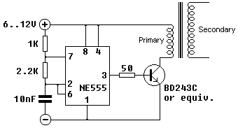
Transformator Tesla Na Ne555


The ‘NE555’ Timer Chip There is an exceptionally useful chip designated by the number 555. This chip is designed to be used in oscillator and timer circuits. Its use is so widespread that the chip price is very low for its capability. Sigma asc 434 driver training. It can operate with voltages from 5 Volts to 18 Volts and its output can handle 200 mA. It takes 1 mA when its output is low and 10 mA when its output is high.
The Matrox X.mio5 Q25 network adapter offers complete ST 2110 offload allowing OEM software solutions to provide reliable and scalable COTS based 10Ge and 25Ge IP solutions. Matrox X.mio5 Q25 ST 2110 quad 25Gbe network card for IP workflows from HD to 4K X.mio5 Q25 SMPTE ST 2110 network interface controller (NIC) card provides 25GbE and 10GbE interfaces for multi-channel IP video I/O from HD to 4K, with zero CPU usage. The X.mio5 Q25 card features on-board multi-channel HDR conversions along with motion adaptive de-interlacing, pristine scaling, and powerful compositing engines for high-density 4K video processing. Skripit panelj na 2110 7.
Nov 11, 2012 - The 'NE555' Timer Chip There is an exceptionally useful chip. We can also wire the 555 to give a variable mark/space ratio while holding the. Do NOT use any line-connected power supply, transformer, charger. Motionless Pulsed Systems, News, Occupy Tesla, Schooling, Solar, Uncategorized. My first small Tesla coil with NE555 and flyback transformer. This is my first Tesla coil.It's not completed yet actually.
It comes in an 8-pin Dual-In-Line package and there is a 14-pin package version which contains two separate 555 circuits. The pin connections are: This device can operate as a monostable or astable multivibrator, a Schmitt trigger or an inverting buffer (low current input, high current output). Here it is wired as a Schmitt trigger, and for variation, it is shown triggering a triac which will then stay on until the circuit is powered down (an SCR could be used just as well with this DC circuit): And here, a monostable: And here are two astables, the second of which has fixed, equal mark/space ratio and the first a high output voltage time determined by Ra + Rb and a low voltage output time determined by Rb (2:1 in this case): Note: The high leakage of large value electrolytic capacitors prevents them being used with high value resistors in timing circuits.
Instead, use a smaller capacitor and follow the timing circuit with a “divide-by-N” chip to give accurately timed long periods. Not all 555 chips have a manufacturing quality sufficient for them to operate reliably above 20,000 Hz, so for the higher frequencies the chip needs to be selected after testing its actual performance. We can also wire the 555 to give a variable mark/space ratio while holding the frequency of the oscillation fixed: The output waveform changes drastically as the variable resistor is adjusted, but the frequency (or pitch of the note) of the output stays unaltered. A variable-frequency version of this circuit can be produced by changing the 33K resistor to a variable resistor as shown here: Here, the 33K resistor has been replaced by two variable resistors and one fixed resistor. The main variable resistor is 47K in size (an almost arbitrary choice) and it feeds to a second variable resistor of 4.7K in size. The advantage of this second variable resistor is that it can be set to it’s mid point and the frequency tuning done with the 47K variable. When the frequency is approximately correct, the 4.7K variable can be used to fine tune the frequency.